Wednesday, 29 June 2011

Workshop - Roofing Practical... Verge Construction

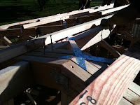
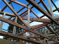
Unable to be on site today as the contractors are attaching the roofing today.  As a result the afternoon was spent in the workshop concentrating on the roofing exercise.  
As the gable end truss was attached yesterday, & we had started cutting to length the outriggers, we just continued on from here.  We still had a few to cut, so this took a fair amount of time.
The markings for spacing the outriggers and purlins were also transferred onto the rafters in question.  For the spacing of the outriggers, it was taken at 150mm from the apex.  At the bottom of the rafter, the outrigger was placed against a temporary vertical edge at the end of the rafter.  The outrigger was then put against this and was marked out (as the outrigger can not sit past the edge of the rafter).
The distance between the first and last outrigger was then measured and divided in half to give the middle outriggers position.  This process was repeated on both sides of the roof.  Purlins spacings also ascertained by following these same spacings, but not put on yet.  We did start on underpurlins though.
Outriggers were cut to 355mm (400 - 45mm)  which was the overhang + length to next rafter - thickness of the fly rafter.


Tuesday, 28 June 2011

Inspection Finishing Touches

Weather pretty crap today so really didn't spend much time on site at all. Main job was finishing off the roof edge protection from yesterday as it wasn't quite done by end of day.  
Also went around nailing in 100x3.75's at 500mm spacings through the double plate and down into the top plate.  This was done to show the inspector that we had used the correct fixings as the end of the nail pokes out of the bottom of the top plate and he is able to visibly see it has been fixed down without having to climb onto the frame to check.

Earlier on in the week, a small effort had been made to start running the ceiling battens, so a small amount of time today was spent on nailing them to the truss bottom chords that they run past, with 75's.  This is quite difficult as you are working at a strange angle, as you are having to hammer up... and it puts strain on your neck because you are looking up all the time... definitely not my most favourite job!

Rest of the time not on site, was spent in the workshop on the roofing exercise we started a week or so back.  We finally attached the gable end truss and started to cut to length the outriggers which was based on the length of the overhang (200mm), minus the thickness of the fly rafter.  We also were cutting the vertical struts to support the gable end truss and the additional loads that will be placed on it from the verge construction

Monday, 27 June 2011

Getting Ready For The ROOF...


Came back on site to find that the facias had been attached whilst we were away.  These were done by an outside contractor, & meant that we had a final finished product attached to the building.  As the material is quite soft and maliable, we now have to be pretty careful when working around it as we can easily bend it out of shape or knock it & dent/scratch it.
Today we concentrated on getting odd jobs done, as we still had loads to complete before the inspection & the roof is put up.
Nogs were still missing at the gable end trusses, so these had to be inserted, so that 70x35 timber ran underneath the top chord between every space.  Vertical struts also needed to be inserted at every point where a full length stud in the wall frame existed, so that this same line was run through the truss as well.  This was important to do so that there was a surface to attach the weatherboards to.

We also had a few bracing elements left to do.  This was mainly above the lintels where jack studs were present.  These had to be secured between the top plate through to the jack stud & onto the lintel.  As the jack stud was quite small and only held in by nails, it was impossible to secure the nail plates by hammering in... as it just forced the jackstud to push out of its correct position (which is flush with the lintel and the top plate).   As a result, Rich taught us a good trick to use, which was to use a clamp to push the nail plates in simultaneously with apposing forces.   
Some sections of the interior walls were missing double plates so these were also inserted in preparation for ceiling battens to be inserted.  When measuring these, they only had to be roughly measured as they only have to provide a surface for the battens to butt up against, or be at a length where battens could run between the spacings of the double top plate easily.  When securing the double plate, the exterior had to be flush with the wall so that there was a 50mm overhang into the inside of the building, and the interior double top plates had to sit even so that there was a 25mm overhang on each side.


The last job of the day was to put up the roof edge protection for the workers coming on site to put the roofing on.  Unitec is legally obliged to provide safety precautions for the workers, so these had to be put up.
The scaffold edging had to as close to the building line as possible (without touching as this can cause damage).  This was achieved by using the various connectors.  The first one used was an internal join, which sits on the inside of the tube &  

helps to connect another pipe to it so that a longer length can be achieved. 
The standards had to be no greater than 2.4m in spacings along the building edge & had to rise high enough to allow for a guard rail at 900mm in height above the lowest point of the  roof.
Once all standards had been attached around the perimeter of the building, the guard rails were then attached.  This was done by attaching swivel coupler at 900mm, 450mm & the lowest one, at a minimum of 150mm from the lowest point of the roof.  This provided a guardrail, midrail & bottom guardrail.  As the metal tubing was not long enough to reach the length of the building, these had to be joined together by using a sleeve (external joiner). 
Some of the standards were attached to existing scaffolding, so a single putlog coupler was used to achieve this.  
This had to be done around the whole of the perimeter of the building, including the gable end.


Wednesday, 22 June 2011

Purlin Time!

Today was purlin day.  First thing was that we prepared the trusses with marks showing the location of where the purlin would sit (based on the spacings specified in the plan.  These were scribed onto the trusses & also had a nail nailed into the area (so that the purlins could sit on the nails & stop it from sliding down the pitch of the roof).  Once all marked out, the purlins could start being laid out along the length of the building & attached.  From the apex of the building, the first measurement was 150mm on each side from the apex.  The joins of the purlins were done so that there were no two joins adjacent from each other, or
 on the same truss.  When getting the purlins to the correct length so that it always fell on a truss where a join could be, the purlins were cut to length up on the roof when laid out.  When it hit a truss where it could be cut, it was marked off to half the thickness of the rafter & then a hand saw was used to cut off at this mark.  It was then secured down with 2/100x375.  
This process gave more control on dictating where joins would fall whilst making it easier to do as it gave more leeway &  eliminated the chance of measurement errors (as apposed to cutting to length on the ground). 
As the purlins were being secured down, it was also really important that someone was at the gable end of the building, checking that it's alignment was ok.  This was really important 
as the roof cladding relies on the purlins being straight so that there is a surface for them to be fixed on to.
Once they are all laid on to the trusses, there will be several overhanging lengths off the gable end truss, these are all cut to length so that they are flush with the outriggers on the overhangs of the building.  Uplift fixings are then attached to the purlins, where 1x Z Wiredog was put on every point where a purlin met a truss, & 4 were attached where ever a join occurred on a truss.  

The purlins were also important as they provided an extra support surface to hold the ladder frame securely to the gable end truss.  This pre-nailed frame work was designed to cover the overhang & was attached by aligning it so that it was plumb with the gable end truss rafters.  Once in position a clamp was used to hold it in place & then it was secured with 100x3.75 galvanised flat head nails.  


Tuesday, 21 June 2011

Odd's & Ends Finished Off - Dragon Ties & BL1's


Back on site today & loads to do to catch up with Marty's house so that we are ready to have the facia's attached as well.    Again, we spent our time finishing off little jobs that needed doing.  Rich was away from site today, so we were working with Joey & mainly tried to get all of our bracing elements done to stop uplift.
We inserted a BL1 on the interior wall.  As we had not done before fixing the wall down, it was a little tricker to achieve.  We had to measure out the length of a trim stud to put against the stud rather than try and get the bracing attached to the existing wall stud (this is so that it doesn't affect wall fixings to the stud & also because it is easier to feed the strap under the bottom plate here, than near the stud).  Before we attached the trimming stud, we routed out a thickness of 4mm deep and 300mm long on it, which was to provide an area where the strap could sit so that it was flush with the wall frame surface.  This was also done on the bottom plate where the strap would sit.  To do the trimming stud checking, we used a skill saw (but a router would also have done the trick) & for the bottom plate
we used the chisel & hammer method.    Once the trim stud was attached, we then thread the strap under the bottom plate, by jacking it up with a dogyu bar.  Once done it was run up the trim stud 300mm & secured using 6/30x0.25mm nails on each side.  At a minimum of 100mm, a bolt was also put down in the bottom pate to the floor joist below the floorboard.  
Exterior wall braces also done, this involved a double metal strap running down adjacent studs to the boundary floor joist.  The same method was applied with routing out an area for the strap to sit, however nails to fix it in had to be spaced so that there were 6/30x0.25 in the stud, 3/30's in the bottom plate & 6/30's in the boundary joist.  No bolt required in this area.

We also inserted the dragon ties today.  These had to be inserted at a 45degree angle and could be no more than 2.4m from outside wall inwards (along the span).  These were secured along the bottom chord on flat, with 2/100's on each truss it crossed over.  An additional nog had to be inserted to fix the end of the dragon tie to.  These were skew nailed in with 100's as well.  Dragon ties were inserted over the lounge area on either corner.  These were needed due to the lack of interior walls in this area to add support to the loads running through the walls from the roof trusses.


Monday, 20 June 2011

Workshop: Roof Frame Practical

Today we got rained off site, so started on our roofing practical in the workshop which was to make a roof frame like the one on the Unitec building (but on a smaller scale).  We split into groups and were each given a different pitch.  
I was with Ben, Erin & Periri & our pitch was 42degrees.  Using this information we were able to calculate the length of the rafter and rise.  We did a mock plan on a piece of paper & based our run on the length of the workshop table.  We did this plan so that we could get the angles for the two different area's 
on the roof that would require them (so we could figure out their pitch).  
Once done, we started cutting out 6 rafters to length with the angle cuts at the end (one to sit flush against table surface (which was acting as our top plate) and the other to sit flush against the ridge).
The ridge board was then cut (which was the length of the table with 200mm added to each end to account for the overhang).  On the ridge, a running measurement was done to figure out where the rafters would sit along it.  This was done by taking off the 200mm for the overhang, instepping this by 150mm then every 400cr.  These same markings were also done along the span of the table (starting from the 150mm instep as the 200mm overhang is not present along this length).  
Once all the markings were done, the rafters were temporarily tacked down to the table, and then the ridge was inserted down the middle of these rafters.  The rafters had to be flush with the bottom of the ridge board and the markings previously scribed.  A level was then used to make sure that the ridge board was centered by runnng vertically at the rise & also along the top of the ridge board as well.  Once correct the rafters were nailed in to the ridge board.  
We then started prepping the gable end rafters to sit lower to support the outriggers & fly rafter.
This was done by scribbing out on the table the thickness of the rafter (as this is the new line that it must sit on the table.  The length from mid way through the thickness of the ridge, down to new marking on the table is then taken (as this is the length of the gable end rafter.  The same angles as the other rafters were then cut with an edge cut taken so that they both join under the ridge and are flush with the bottom of the ridge.  These were then also attached as the other ridges.  

Wednesday, 15 June 2011

Brace Elements


Once we finished our nogs & other jobs left over from yesterday, we started doing bracing elements.  
Roof plane bracing was run out by calculating the run of the house & then transfering this measurement along the length of the house as well.  This gave the 45 degree angle required to attach the metal strap bracing.  Two people then held the strapping at either end (which is run at a diagonal over the apex of the gable end roof truss down to the top plate & the other end goes over the double top plate down to the top plate.  One end is secured down with a minimum of 6/75x3.15 & then the other end is tensioned as much as possible before nailing in (with the same fixings).
Once done, a tensioner is put on the strap to pull it tighter (as pictured on right) & then the straps can be nailed in where ever it crosses a truss.  before it is secured, someone should stand at the end of the truss so that they can check the truss is aligned before driving in the fixing.    This process should be repeated for the opposite diagonal (which will make a cross
plane bracing - as pictured).
These roof plane bracings are located at every corner of the Unitec house.  


Roof space bracing also secured into place.  On the Unitec building these are located at either end of the building and also in the middle of the roof spacing.  It should not be at a pitch greater than 45 degree's.  A nog needs to be placed in at the apex so that the top of the roof space bracing can be attached to it. It is then secured at the angle on to the ceiling runner
If it runs greater than 2meters along the ceiling runner it needs to be doubled up so that it has extra strength.

Tuesday, 14 June 2011

Catch Up What Happened With Wall Frames & Trusses

Last of the wall framing steps was to straighten/square the walls, and then attach the double top plate (in particular on the exterior walls - so that roof trusses can be attached).  This involved using temporary braces to hold everything in the correct position. 
Pre-nailed trusses arrived on site in a packet (much like the wall frames) with additional packets for purlins, outriggers, noggings, ceiling runners and dragon ties etc.  Had to be careful lifting them up on to the roof, as twisting them can result in them weakening.  Before they could be put onto the roof, markings were put along the double top plate at the spacings pre-determined on the roof plan.  Working in teams they were lifted up on the scaffold & then slid across to the interior walls which acted as support.  For the lounge area where there were no intermediate supports, people were waiting on saw horses to give support.  
Gable end trusses put up first.  Stopper blocks put at the  wall frame to stop it slipping off when aligning with the wall frame.  On the edges the bottom chord is made flush with the double top plate.  Once in correct position it is secured with 2/100's skew nailed.  
A stringline is then run between the two gable end trusses at the apex, which gives a center mark for the other trusses to be lined up with.  Intermediate trusses can now be attached by lining up with pre-marked lines on double top plate & stringline.  As each truss is attached, a spacer block is put between them to check that it is the correct spacings & then a temporary brace is attached. Once done, a ceiling runner was run along the bottom chord on edge throughout the span of the trusses.
Today we also put nail plates & cyclone ties down over all major joins to strengthen the joins for structural loads that may 


be placed on it this was particularly important where the trusses sat on the double top plate.  Staples were also put on the building, running from every top plate to full length stud.  These had to be recessed in so that the wire dog staple sat flush.
Some of the team also started attaching the soffit nogs along the length of the BL.  This was attached 20-30mm from wall frame line which was to allow for cavity battens to be inserted and wall lining.  
The Unitec building has some large overhangs, so the trusses are strengthened with 'scab's' in this area to combat the additional load to the area.  
Outriggers were also inserted on the gable end truss.  This sat lower than the intermediate truss directly after it, so that it formed a platform for the outriggers to sit on.  The outriggers were spaced according to specifications on plan & were end nailed in to the truss it was butted into & skew nailed in for the gable end truss that it sat on top of.  Outrigger nogs were also inserted at 20-30mm from gable end truss face (like for the soffit nogging).